
If your CNC lathe has unstable clamping force, insufficient jaw stroke, repeated runout, vibration, or workpiece slipping during machining, the problem may not be the chuck alone. In many cases, the issue comes from the hydraulic chuck, draw tube, and rotary hydraulic cylinder not being properly matched.
A hydraulic chuck system is not just one component. It is a complete workholding system that includes the power chuck, draw tube, rotary hydraulic cylinder, jaws, and machine spindle. These parts must work together to transfer hydraulic force into stable jaw movement.
For manufacturers using CNC turning lathes, turning centers, Swiss-type lathes, or automated bar feeding systems, checking this system before purchasing or replacing components can help reduce setup problems, machining instability, and production delays.
This article explains how to check whether your hydraulic chuck system is properly matched, what problems may occur when components are not compatible, and what B2B buyers should confirm before selecting a hydraulic power chuck or rotary hydraulic cylinder.
Quick Takeaway
A hydraulic chuck system works correctly only when the chuck, draw tube, rotary cylinder, jaws, and spindle are matched as one system.
| What to Check | Why It Matters |
|---|---|
| Chuck type | Determines whether the system is suitable for through-hole or non through-hole machining |
| Rotary hydraulic cylinder | Provides the push/pull force that drives the chuck |
| Cylinder stroke | Affects whether the chuck can open and close fully |
| Draw tube connection | Transfers movement from the cylinder to the chuck |
| Jaw stroke | Determines loading clearance and gripping range |
| Pull force | Affects actual clamping force at the jaws |
| Maximum speed | Must match the CNC lathe’s operating speed |
| Jaw setup | Affects runout, surface marks, deformation, and repeatability |
For buyers, the most important point is this: do not select the chuck and hydraulic cylinder separately. They should be reviewed as a matched clamping system.
When Do You Need to Review the Hydraulic Chuck System?
Many factories first check the cutting tool, machining parameters, or chuck body when clamping problems occur. However, if the chuck, draw tube, and rotary cylinder are not matched correctly, changing tools or cutting conditions may not solve the real problem.
| Problem Seen on the Machine | Possible System Issue |
|---|---|
| Chuck does not open or close fully | Cylinder stroke or draw tube movement may be insufficient |
| Workpiece slips during cutting | Pull force, clamping force, or jaw contact may be insufficient |
| Runout appears after clamping | Jaw setup, draw tube alignment, or chuck-cylinder matching may need review |
| Vibration occurs during turning | Workpiece support or clamping stability may be poor |
| Thin-wall parts deform | Clamping force may be too high or jaw contact may be too concentrated |
| Machine cannot reach required speed | Chuck or cylinder speed rating may not match the application |
| Installation takes longer than expected | Thread, mounting, or draw tube dimensions may not match |
| Production quality varies by batch | Jaw wear, unstable clamping, or inconsistent actuation may be involved |
This is why a hydraulic chuck system should be checked from the complete motion path, not only from one component.
How a Hydraulic Chuck System Works
A hydraulic chuck system transfers hydraulic pressure into mechanical jaw movement. The process can be understood as a simple force transmission chain.
First, hydraulic pressure activates the rotary hydraulic cylinder mounted at the rear of the spindle. The cylinder piston moves forward or backward according to the hydraulic direction.
Second, the draw tube connected to the cylinder transfers this linear motion through the spindle.
Third, the power chuck mounted at the front of the spindle converts the draw tube movement into jaw opening or closing.
Finally, the jaws contact and clamp the workpiece for machining.
| Step | Component | Function |
|---|---|---|
| 1 | Rotary hydraulic cylinder | Generates push or pull force |
| 2 | Draw tube | Transfers cylinder movement through the spindle |
| 3 | Power chuck | Converts linear movement into jaw movement |
| 4 | Jaws | Contact and hold the workpiece |
| 5 | Spindle | Rotates the complete clamping system during machining |
If any part in this chain is not suitable, the complete clamping result may be affected.
Main Components Buyers Should Check
A hydraulic chuck system should be evaluated as a group of connected parts. Each component affects the next one.
| Component | Role in the System | What Buyers Should Confirm |
|---|---|---|
| Power chuck | Holds the workpiece through jaw movement | Chuck type, size, jaw stroke, clamping capacity |
| Rotary hydraulic cylinder | Drives the chuck through push/pull movement | Stroke, pull force, maximum speed, through-hole or non through-hole type |
| Draw tube | Connects cylinder movement to the chuck | Thread, length, rigidity, connection accuracy |
| Hard jaws / soft jaws | Contact the workpiece directly | Contact area, surface protection, roughing or finishing use |
| Spindle | Supports rotation and system alignment | Spindle bore, speed, mounting interface, balance |
| Hydraulic unit | Supplies pressure to the cylinder | Stable pressure, flow, machine compatibility |
For purchasing teams, this means the correct product name is not enough. The specifications must also be checked together.
Why Chuck and Rotary Cylinder Matching Matters
The rotary hydraulic cylinder must provide the right stroke, pull force, and rotation capability for the chuck. If these specifications do not match, the system may still be installed, but it may not perform correctly during production.
| Matching Factor | Possible Problem If Incorrect |
|---|---|
| Cylinder stroke too short | Chuck may not open or close fully |
| Pull force too low | Workpiece may slip during machining |
| Pull force too high | Thin-wall or precision parts may deform |
| Speed rating too low | Machine cannot run at the required RPM |
| Draw tube length incorrect | Chuck movement may be incomplete or unstable |
| Thread mismatch | Installation delay or connection failure |
| Jaw stroke insufficient | Workpiece loading and unloading may become difficult |
| Chuck size not suitable | Clamping range or rigidity may not meet the application |
A properly matched system helps improve clamping stability, production repeatability, and machining safety.
Through-Hole Systems: For Bar Feeding and Continuous Turning
If the workpiece is produced from long bar stock, a through-hole system is usually required. A through hole power chuck allows material to pass through the chuck and spindle. The rotary hydraulic cylinder also needs a through-hole structure so the bar can pass through the rear side of the machine.
This setup is commonly used for shafts, tubes, fittings, connectors, and components produced from bar stock. It is suitable for continuous CNC turning and automated feeding applications.
| Through-Hole System Item | What to Confirm |
|---|---|
| Through hole power chuck | Chuck size, bore capacity, jaw stroke, clamping force |
| RC Series hydraulic cylinder | Through-hole structure, stroke, speed, pressure, machine compatibility |
| RCS Series hydraulic cylinder | Compact through-hole cylinder option for suitable machine layouts |
| Draw tube | Correct length and connection with chuck and cylinder |
| Bar feeder | Material diameter and spindle bore compatibility |
| Jaws | Suitable gripping for bar stock, shafts, or tubes |
For buyers planning bar feeding production, the through-hole path must be confirmed from front to rear. The chuck, spindle bore, draw tube, hydraulic cylinder, and bar feeder all need to support the required material size.
Related reading: Thru-Hole vs. Non-Thru-Hole Power Chucks: How to Choose the Right One for Your CNC Lathe?
Non Through-Hole Systems: For Short Workpieces and Rigid Clamping
Not every CNC lathe application requires bar feeding. For short workpieces, flanges, gear blanks, castings, or special-shaped parts, a non through-hole power chuck may be more suitable.
In this type of system, the material does not pass through the spindle. The focus is usually on rigidity, clamping force, compact installation, and stable support for short or heavier parts.
| Non Through-Hole System Item | What to Confirm |
|---|---|
| Non through-hole power chuck | Chuck size, rigidity, jaw stroke, clamping capacity |
| Non through-hole hydraulic cylinder | Pull force, stroke, speed, mounting dimensions |
| Draw tube | Proper connection and movement transfer |
| Hard jaws / soft jaws | Workpiece contact, gripping strength, surface protection |
| Workpiece type | Short parts, flanges, castings, gear blanks, irregular shapes |
For buyers machining short or heavy workpieces, the question is not only whether the chuck can hold the part. It is whether the complete system can provide stable clamping, enough jaw contact, and repeatable positioning during production.
Common Problems Caused by Mismatched Components
When the chuck, draw tube, and rotary cylinder are not matched correctly, the symptoms may appear in different ways on the shop floor.
| Problem | Possible Cause | Production Impact |
|---|---|---|
| Chuck opening is too small | Cylinder stroke or draw tube movement is insufficient | Loading and unloading difficulty |
| Weak clamping | Pull force does not match chuck requirement | Workpiece slipping or movement |
| Unstable repeatability | Jaw setup or draw tube connection is inconsistent | Batch quality variation |
| Runout after clamping | Chuck, jaw, or draw tube alignment problem | Dimensional error |
| Surface marks | Jaw contact or clamping force not suitable | Cosmetic or functional surface damage |
| Thin-wall deformation | Clamping pressure too concentrated | Out-of-tolerance parts |
| Speed limitation | Chuck or cylinder speed rating is not suitable | Lower machining efficiency |
| Installation delay | Mounting, thread, or draw tube mismatch | Longer setup time |
These problems are especially costly in mass production because they may lead to repeated rework, scrap, inspection failure, and machine downtime.
What Buyers Should Prepare Before Asking a Supplier
To help the supplier recommend the right hydraulic chuck system, buyers should prepare key machine and workpiece information in advance.
| Information to Provide | Why It Helps |
|---|---|
| CNC lathe model | Helps confirm machine-side compatibility |
| Spindle type and bore size | Determines through-hole capacity and mounting direction |
| Workpiece diameter and length | Affects chuck size and jaw stroke |
| Workpiece material | Affects clamping force and jaw selection |
| Bar feeding or pre-cut blank | Determines through-hole or non through-hole system |
| Required spindle speed | Must match chuck and cylinder speed ratings |
| Machining process | Roughing, finishing, heavy cutting, or precision turning |
| Required clamping method | Helps determine jaws and contact support |
| Current chuck or cylinder model | Helps review replacement or upgrade compatibility |
This information allows the supplier to review the system more accurately instead of recommending only by chuck size.
TON FOU Hydraulic Chuck System Solutions
TON FOU provides through hole power chucks, non through-hole power chucks, through-hole hydraulic cylinders, non through-hole hydraulic cylinders, hard jaws and soft jaws, collet chucks, and related CNC lathe workholding components.
Instead of selecting each part separately, buyers can review the complete chuck, cylinder, draw tube, and jaw combination according to machine configuration and workpiece requirements.
| TON FOU Product Direction | Suitable Use |
|---|---|
| Through Hole Power Chuck | Bar feeding, long shafts, tubes, continuous CNC turning |
| Non Through-Hole Power Chuck | Short workpieces, flanges, gear blanks, rigid clamping applications |
| RC Series Hydraulic Cylinder | High-speed through-hole rotary hydraulic cylinder applications |
| RCS Series Hydraulic Cylinder | Compact high-speed through-hole rotary hydraulic cylinder applications |
| Non Through-Hole Hydraulic Cylinder | Compact non through-hole clamping applications |
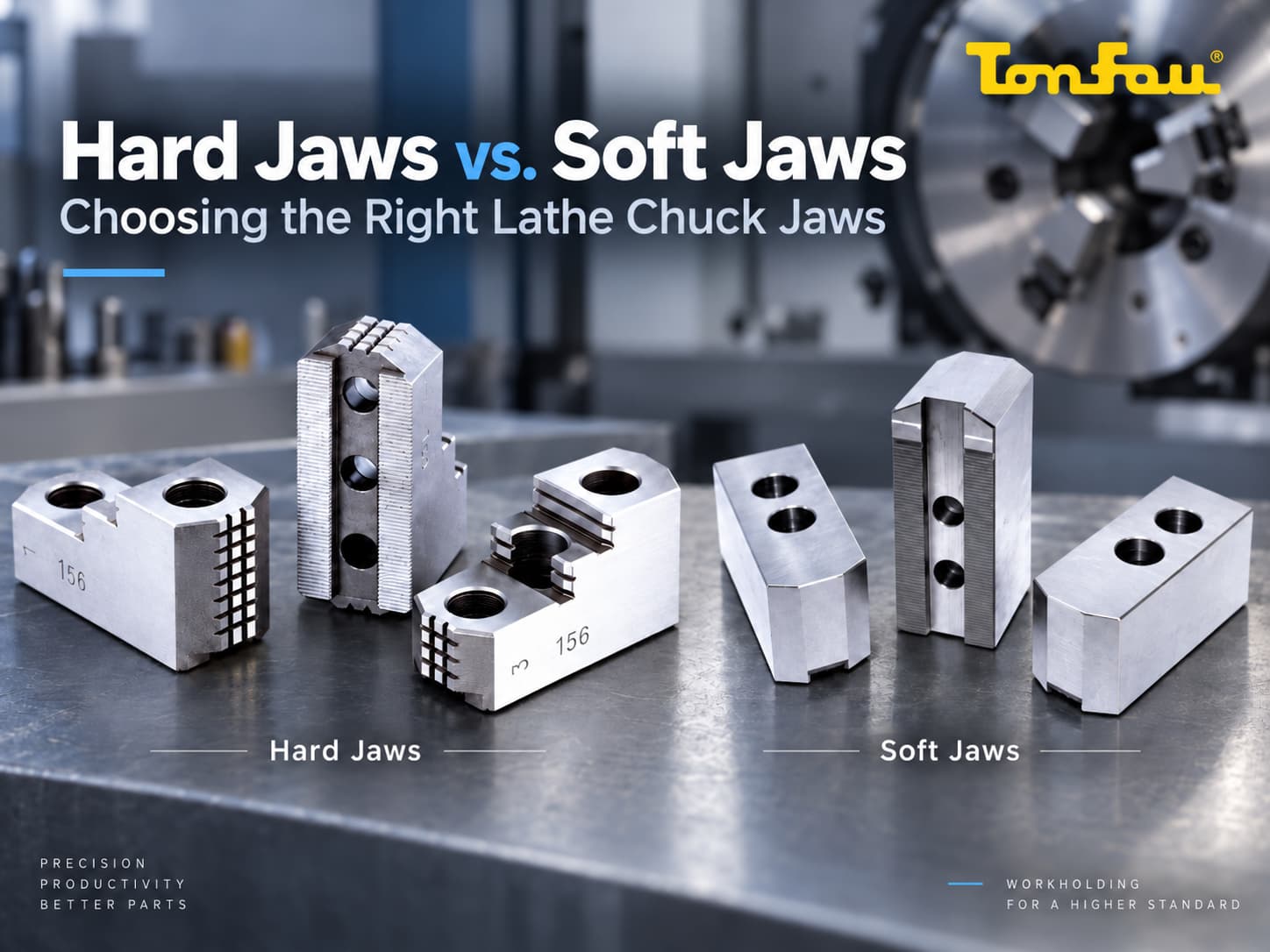
| Hard Jaws & Soft Jaws | Rough machining, precision clamping, surface protection |
| Collet Chuck | Small parts, bar stock, and high-repeatability machining |
For manufacturers comparing hydraulic chuck manufacturers, TON FOU’s value is not only providing individual products. The more important value is helping buyers consider how the power chuck, rotary hydraulic cylinder, jaws, and related workholding components should work together.
Related Reading
| Topic | Recommended Reading |
|---|---|
| Hydraulic vs pneumatic clamping | Pneumatic Chuck vs Hydraulic Chuck: Which One Should You Use? |
| Hydraulic chuck automation applications | Top 5 Applications of Hydraulic Chucks in CNC Automation |
| Through-hole vs non-through-hole chuck selection | Thru-Hole vs. Non-Thru-Hole Power Chucks: How to Choose the Right One for Your CNC Lathe? |
| Power chuck and cylinder for mill-turn machining | Power Chucks and Hydraulic Cylinders for Complex CNC Mill-Turn Workpieces |
| Power chuck selection mistakes | Common Power Chuck Selection Mistakes That Affect CNC Lathe Accuracy |
| Jaw setup and machining quality | How to Choose Lathe Chuck Jaws Without Causing Runout, Deformation, or Surface Marks |
Conclusion
A hydraulic chuck system should not be selected by looking at the chuck alone. The power chuck, draw tube, rotary hydraulic cylinder, jaws, spindle speed, workpiece type, and machining process must all be checked together.
When these components are properly matched, the system can provide stable clamping force, correct jaw movement, reliable workpiece positioning, and efficient CNC lathe production. When they are not matched, manufacturers may face runout, weak clamping, insufficient jaw stroke, workpiece deformation, installation problems, or reduced machine performance.
For CNC lathe buyers, the best approach is to review the complete system before purchasing or replacing components. This helps reduce production risk and improves long-term machining stability.
Looking for a Hydraulic Chuck System for Your CNC Lathe?
If you are selecting a hydraulic chuck for lathe applications, please prepare your chuck model, spindle type, workpiece size, required speed, clamping method, and whether bar feeding is needed.
TON FOU can help manufacturers evaluate suitable power chucks, RC Series through-hole hydraulic cylinders, non through-hole hydraulic cylinders, jaws, and related components based on machine configuration and workpiece requirements.
Contact TON FOU